Growth on Substrate
The synthesis via CCVD was accomplished using two different general synthesis techniques [2][74] that can be differentiated by the substrate on which the catalyst was deposited. The synthesis on zeolite was primarily used for convenient large-scale production and individualization using wet post-processing methods. The Synthesis on wafers was used to directly yield individualized nanotubes of high quality for microscopic investigations and single-molecule measurements. The diameter distribution in both methods is similar.[96]
Zeolite
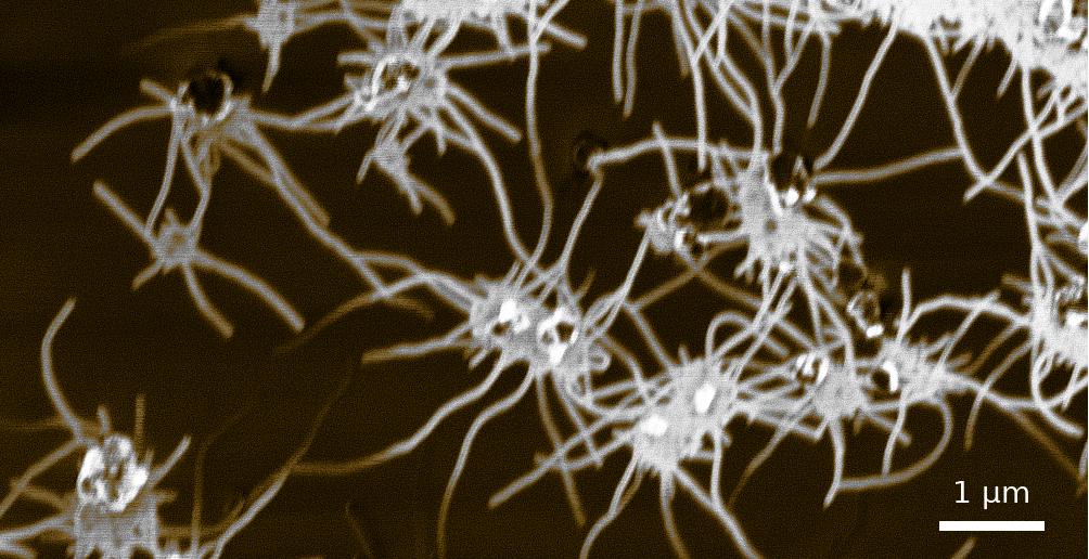
Spider-like growth of carbon nanotubes on zeolite FAU 111 using the Maruyama approach. Cavities in the zeolite substrate isolate and direct the growth of single-wall carbon nanotubes. The as-grown carbon nanotubes directly allow further wet-processing.
A conventional way for the synthesis of carbon nanotubes via ACCVD is the usage of zeolite as a substrate. These alumno silicates accept metal catalyst particles to their microporous structure. The pores of zeolite Y are 0.74nm in diameter and act as a mold for carbon nanotubes with a similar diameter.

The figure shows the variation of temperature, pressure, and precursor as a function of the reaction time for a typical ACCVD process. The reaction is carried out at a temperature of 750℃ and a pressure of 15mbar.
In the presented experiments, Cobalt co-alloy catalysts in concentrations of 0.5mol metal per gram zeolite Y were prepared. For the growth on zeolite, there was no notable difference between different combinations with Fe, Cu, and Rh on zeolite at 800℃. The diameter distribution only slightly varies at lower synthesis temperatures. For measures of toxicity and cost, Iron-Cobalt has shown to give the best results at 800℃[2][78] and Copper-Cobalt when synthesizing at lower temperatures[67]. As Copper has a lower melting point than Iron, exchanging Iron against Copper shows coalescence to smaller cobalt nanoparticles [67]. These particles are then anchored during Oswalt ripening to their Metal-Co-Alloy.

The figure shows an absorption spectrum (right) of a typical sample synthesized from FeCo catalyst on zeolite Y with corresponding Kataura plot (left) and connections of the first and second excitonic subbands. The ACCVD process gives diameters at about the pore size of the used zeolite material.
Wet processing of the as-grown zeolite raw material allows for an easy investigation of the sample quality and chiral distribution in a cuvette without the need for statistical methods that arises from single-molecule spectroscopy. Within one measurement the sample can be nearly fully characterized in its chiral distribution.
An absorption spectrum is not sufficient for characterizing the chiral distribution of a sample. Some chiralities have overlapping absorption with other chiralities in their excitonic transitions in E₂₂ or E₁₁. For instance, the absorption spectrum of the (7,6) type overlaps with the E₂₂ transition of the (7,5) type and with the E₁₁ transition of the (8,4) type. This overlap is better visible in the second derivative, but such a chiral mixture makes distinct identification of the sample composition impossible using absorption spectroscopy solely.
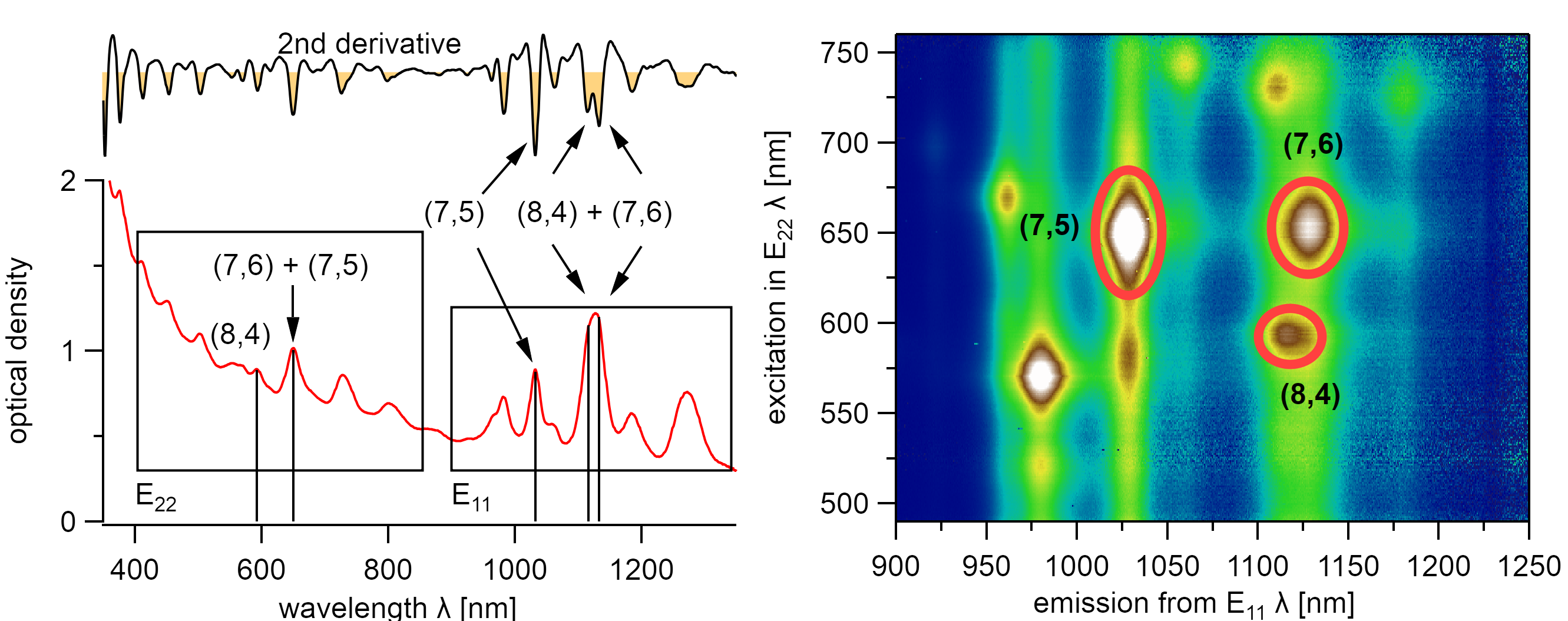
The (8,4) and (7,6) type exhibit the same excitonic absorption energy in their E₂₂ state but differ in their E₁₁ state. However, the (7,6), (7,5), and (8,4) type are clearly identified using PLE spectroscopy. The nanotubes were dispersed with 1.5wt% DOC in water.
A distinct identification of these chiralities is possible using, Photoluminescence Excitation (PLE) Spectroscopy which was introduced by O’Connel et al. in 2002.[97] It allows the exact and distinct identification of all optically active chiralities. This technique is overly important to identify the chirality in varying dielectric environments which is otherwise subject to rough guesses when identifying the chirality during the adsorption of solvent molecules to carbon nanotubes.
However, the de-bundling of the carbon nanotube arrays grown on the zeolite substrate requires the use of rather high force typically applied using shear mixing or sonication and surfactants to prevent subsequent bundling.
Wafer

Different substrates for growing carbon nanotubes freely suspended over trenches: Silicon wafers, Silicon Nitride membranes, and holey Carbon grids. The latter two are typically used in TEM
The synthesis and analysis of carbon nanotubes on a substrate is a more demanding task than the synthesis on zeolite substrates with subsequent wet processing.
Grids for transmission electron microscopy have good commercial availability and the needed porous structure for suspending nanotubes. In short, holey and lacey carbon grids could not withstand the synthesis temperature during the growth process. SiN grids, on the other hand, have shown good results but could not stand the mechanical forces applied during the experiments. These grids, however, are ideal for testing the microscopic setup due to their inherent absence of background emission. In the following experiments, all single molecular measurements were performed with the thermally and mechanically stable, silicon wafers[98][85].
The synthesis on silicon wafers needs similar growth conditions as on zeolite. However, the lack of a predefined catalyst mold requires a slightly modified synthesis route for the catalyst preparation.

The synthesis on flat substrates is carried out with an additional reduction step where hydrogen is used to reduce catalyst particles to facilitate carbon nanotube growth.
The procedure follows a slightly customized variant of the route described by Thurakitseree et al.[74]. In a typical process, the substrate surface was subsequently cleaned using sonication in acetone, isopropanol, and ethanol. It is then dip-coated into 0.5mM cobalt acetate in ethanol and annealed in air at 400℃. After cooling to room temperature, the co-alloy metal solution with equal molarity was added, repeating the described steps.
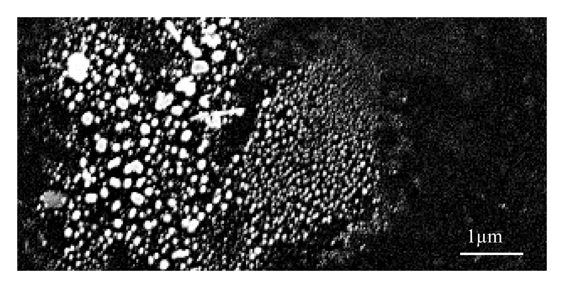
Co-Rh catalyst particles on a silicon substrate after Oswalt ripening under a hydrogen atmosphere at 600℃. The picture shows a spot with a large variety of particle diameters. Due to the high catalyst density in this area, Oswalt ripening is producing particles up to 200nm in diameter.
For the formation of catalyst particles with a defined diameter, the coated catalyst is annealed in a reductive argon atmosphere with 3% hydrogen at 600℃ for 30min. This step facilitates Oswalt ripening and isolates metal catalyst islands on the substrate and forms cobalt silicide [99][100] on silicon substrates. The size of these particles is considered to be of superior importance as they serve as templates for the nanotube growth.
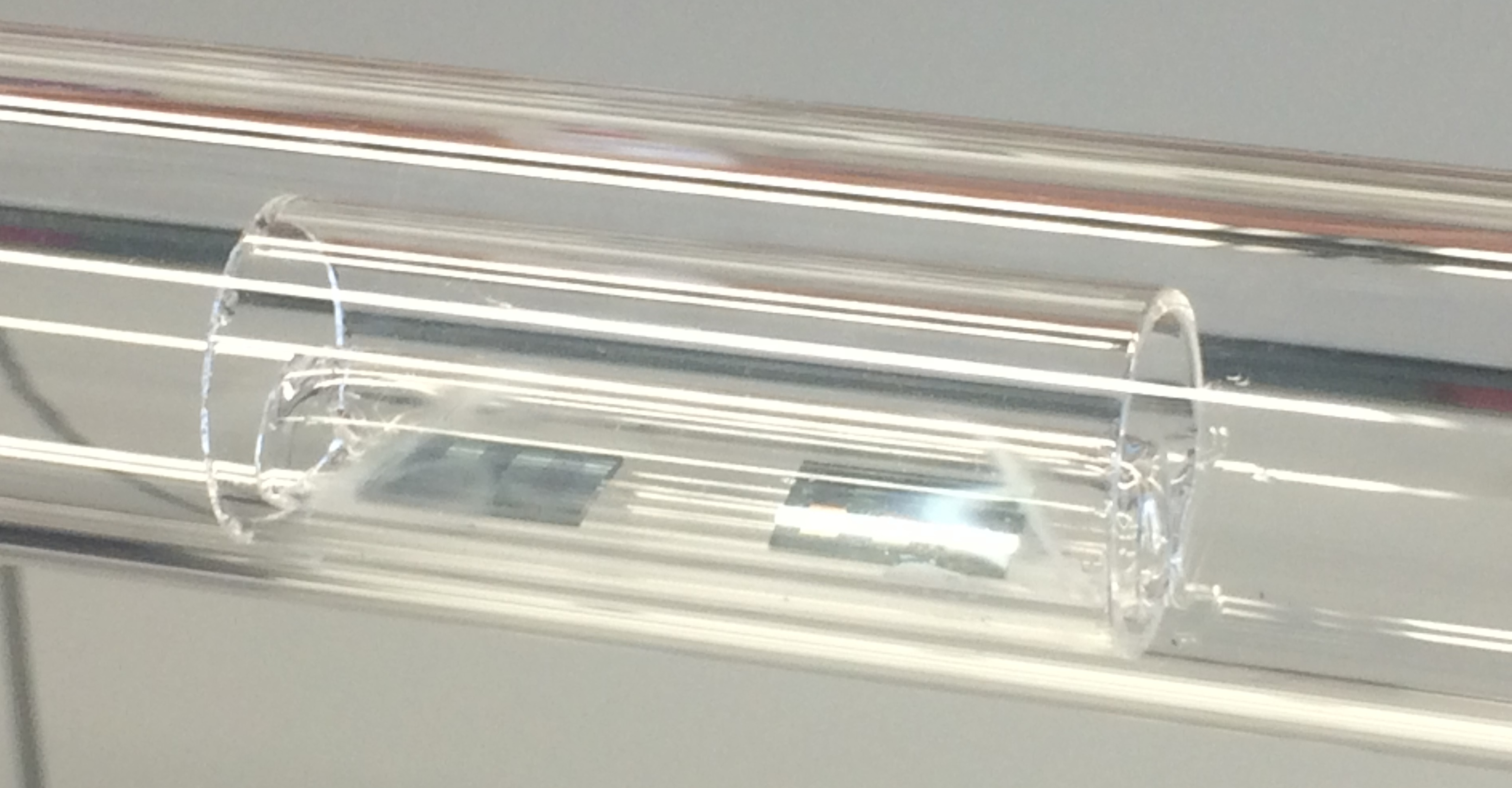
The picture shows the quartz boat with two loaded wafer samples inside the reaction chamber. The oven is placed on rails and can be pulled away for the exact positioning of the sample in the center of the oven.
The reaction chamber is then evacuated and heated to 800℃, where 100mg/min ethanol is introduced for 10min at 8mbar. After the reaction, the sample is cooled to room temperature and kept in a dust-free environment.
Catalyst coating plays a superior role during this process. Since the catalyst is deposited at arbitrary positions on the sample via dip coating, the procedure was lacking reproducibility. In an attempt to compare the chiral distribution of the produced samples, the coated wafers were sonicated in aqueous deoxycholate solution and analyzed using photoluminescence emission spectroscopy while comparable quantum yields for all metals had to be assumed. The chiral distribution slightly varies for different co-alloy metals of cobalt with molybdenum, manganese, iron, copper, or zinc. Chiralities synthesized from Mo and Mn generally show the highest emission. The samples with Fe and Rh as cobalt co-alloy metals have a more homogeneous chiral distribution but are generally also 80% lower in their emission strength and thus their estimated nanotube yield. Cu and Zn did not give good results.[96] Following these results, the following study only uses iron, molybdenum, and rhodium as cobalt co-alloy catalysts for the synthesis of suspended carbon nanotubes at 800℃.